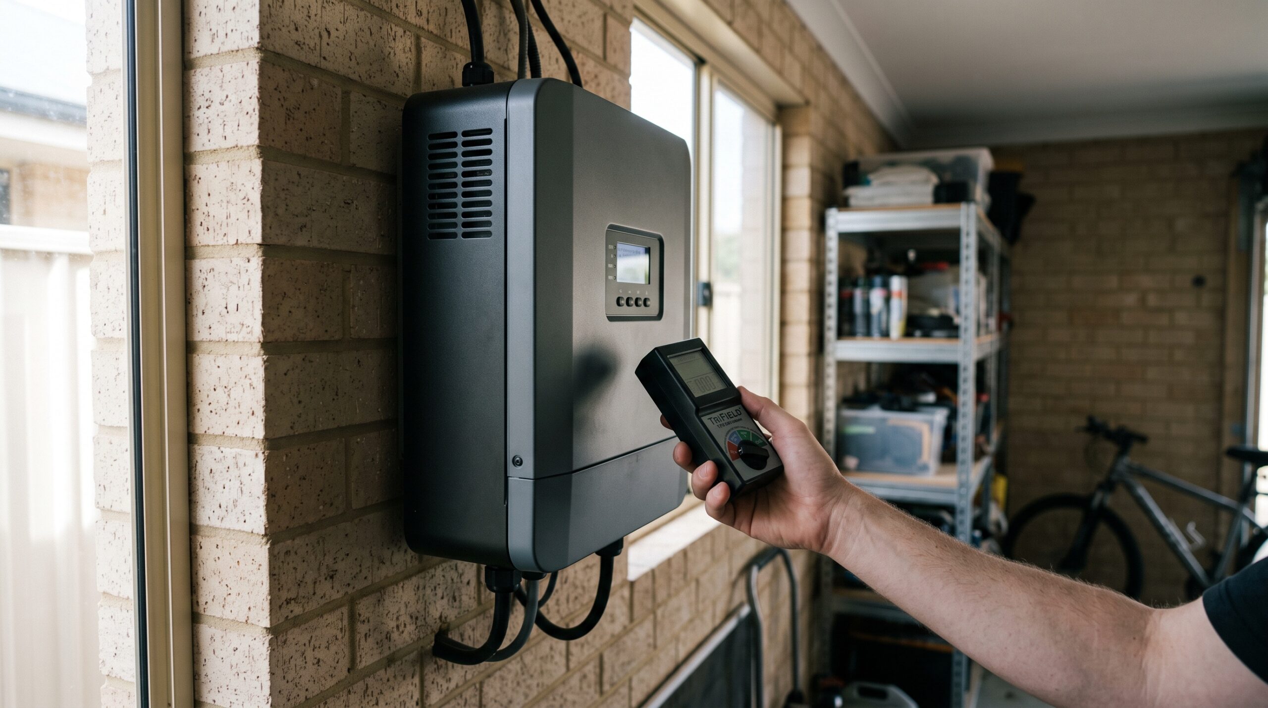
Solar Panel Inverter EMF Australia 2026
Solar inverters in Australia produce measurable AC magnetic fields and inject high-frequency harmonics (dirty electricity) onto household wiring, but at typical installation distances of 2 metres or more, field strengths fall well below both the ARPANSA general public limit of 1,000 µT at 50 Hz and the stricter Building Biology SBM-2015 sleeping-area guideline of 0.2 µT. The real risk is not the inverter itself — it is poor placement that puts it directly behind a bedroom wall, combined with harmonic distortion that rides your home’s wiring into every room.
Solar inverters produce AC magnetic fields that drop below Building Biology thresholds (~0.2 µT) at roughly 1.5-2 metres from the unit in most residential installations. The bigger concern for Australian households is dirty electricity — high-frequency voltage transients (2-100 kHz) that inverters inject onto your mains wiring, which travels throughout the house regardless of inverter placement. String inverters (Fronius, SolarEdge, Sungrow) produce localised magnetic fields of 0.3-2.0 µT at 1 metre during peak generation. Microinverters (Enphase) distribute smaller fields across your roof. Without a meter, you are guessing. The TriField TF2 measures AC magnetic, AC electric, and RF in one device — it is the only tool that gives you actual numbers to act on.
| Source | Typical Field | Verdict |
|---|---|---|
| String inverter at 1m | 0.3–2.0 µT AC magnetic | Manage with placement |
| Dirty electricity on wiring | 50–2,000 mV (GS units) | Whole-house concern |
| TriField TF2 measurement | All three field types | Recommended first step |
Key catches
- AC magnetic field from inverters follows the inverse-square law — doubling your distance quarters the field strength. A 2m gap solves most issues.
- Dirty electricity travels on wiring throughout the house — inverter placement does not contain it. You need a separate measurement (Stetzerizer or oscilloscope) to quantify this.
- ARPANSA’s general public limit (1,000 µT at 50 Hz) is a thermal safety standard, not a precautionary one. Building Biology SBM-2015 sets the sleeping-area guideline 5,000x lower at 0.2 µT.
- The TriField TF2 measures AC magnetic fields accurately at 50 Hz (the inverter’s output frequency) but does not measure high-frequency harmonics above ~100 kHz. For dirty electricity, a dedicated meter is needed.
I’m Jayce Love, former Royal Australian Navy Clearance Diver, now based on the Gold Coast. This article draws on ARPANSA and ACMA measurement surveys of solar installations and the regulatory framework that governs what your inverter is allowed to emit. I have not personally tested the solar inverters, power optimisers, microinverters, or battery systems discussed here; this assessment is based on published manufacturer specifications, ARPANSA installation surveys, and independent certification, not first-hand measurement. The only products I measure first-hand are the EcoHero 5-Stage RO, TriField TF2, and Coway Airmega 150. No wellness language. No fear. Just numbers you can verify yourself.
What Your Solar Inverter Actually Emits: Three Distinct Field Types
Your solar inverter does one job: convert DC electricity from your panels into 230V 50Hz AC for your home and the grid. That conversion process creates three measurable electromagnetic emissions, each behaving differently and requiring different measurement approaches. If you do not understand which field type you are dealing with, you will either panic about nothing or miss the thing that actually matters.
AC magnetic fields (50 Hz) are the primary emission from a working inverter. The internal transformer and power electronics generate a 50 Hz magnetic field that radiates outward in all directions. According to ARPANSA measurement surveys of solar installations, residential inverters typically produce 0.3-2.0 µT at 1 metre distance during peak generation (midday, clear sky, full panel output). At 2 metres, that drops to roughly 0.08-0.5 µT. At 3 metres, most readings fall below the Building Biology SBM-2015 “no anomaly” threshold of 0.2 µT. The key fact: magnetic fields from inverters follow the inverse-square law. Distance is your primary defence, and it costs nothing.
AC electric fields are present wherever energised wiring runs. Your inverter connects to your switchboard via a dedicated circuit. That wiring generates AC electric fields along its entire run — through walls, ceilings, wherever the cable goes. A TriField TF2 in “Standard” electric field mode will show you exactly where these fields are elevated. The Building Biology sleeping-area threshold is below 5 V/m. Most inverter AC output wiring measures 2-15 V/m at 30 cm from the cable, dropping below 1 V/m at 1 metre. The concern is when this cable runs through a bedroom wall or ceiling cavity directly above a bed.
High-frequency harmonics (dirty electricity) are the emission most people overlook and the one that matters most for whole-house exposure. Inverters use high-frequency switching (typically 16-50 kHz) to shape the DC-to-AC conversion. This switching injects voltage transients onto your mains wiring at frequencies between 2 kHz and 100 kHz. These transients ride your entire house wiring system — every circuit, every room, every power point. Unlike the magnetic field that stays near the inverter, dirty electricity travels. The ACMA solar inverter compliance report (2020) confirms that Australian/NZ standards (based on European EMC requirements under AS/NZS CISPR 11) set conducted emission limits, but those limits are designed to prevent radio interference — not to address biological exposure concerns at the frequencies Building Biology practitioners measure.
Inverter Types Compared: Fronius vs SolarEdge vs Microinverters
Not all inverters produce the same EMF profile. The three dominant inverter architectures in the Australian residential market — string inverters, DC-optimised string inverters, and microinverters — each create different field patterns in different locations. Choosing your inverter type is an EMF decision whether your installer acknowledges it or not.
String Inverters (Fronius, Sungrow, GoodWe)
A standard string inverter is a single box, typically mounted on a garage wall or beside the meter box, that handles all DC-to-AC conversion in one location. Fronius Primo and Symo units are the most common in Australian residential installations. AC magnetic field per ARPANSA installation surveys: 0.5-2.0 µT at 1 metre during peak generation, dropping to 0.1-0.4 µT at 2 metres. These ranges reflect ARPANSA measurement surveys of Fronius-class 5kW string inverters at midday output. At night (no generation), the inverter’s magnetic field drops to near zero — typically below 0.05 µT at 1 metre.
The advantage of string inverters from an EMF perspective: all the magnetic field is concentrated in one location that you can plan around. Put it in the garage, away from bedrooms, and the proximity problem is solved. The disadvantage: all the DC-to-AC conversion harmonics are injected at one point, and the conducted emissions from a single large inverter tend to be higher per unit than distributed systems.
DC-Optimised Systems (SolarEdge)
SolarEdge uses power optimisers on each panel (on the roof) plus a central string inverter on the wall. The optimisers handle maximum power point tracking at the panel level, while the inverter still does the DC-to-AC conversion. The wall-mounted inverter unit produces comparable magnetic fields to a standard string inverter — 0.4-1.5 µT at 1 metre. However, the optimisers on the roof also produce small magnetic fields. At roof level, these are typically 0.1-0.3 µT per optimiser at 30 cm — well above the roofline but well below bedroom ceiling level in a two-storey home. In a single-storey home with a flat roof and bedrooms directly under the panels, the cumulative field from a row of optimisers can be measurable at ceiling height.
SolarEdge also adds a communication layer: the optimisers talk to the inverter via power line communication (PLC) over the DC wiring. This injects additional high-frequency signals onto the DC side. While this does not directly add to AC-side dirty electricity, it creates an additional source of conducted emissions within the roof space.
Microinverters (Enphase IQ7/IQ8)
Enphase microinverters convert DC to AC at each panel on the roof. There is no central wall-mounted inverter. From an EMF standpoint, this distributes the magnetic field source across your entire roof rather than concentrating it in one spot. Each microinverter produces a small magnetic field — typically 0.05-0.2 µT at 30 cm. The trade-off: every panel now injects its own switching harmonics directly onto your AC mains wiring from the roof. With 20-30 microinverters all switching at slightly different phases, the harmonic profile can be more complex than a single string inverter. Enphase IQ8 units also include a communication module that transmits data wirelessly at 2.4 GHz — adding a low-level RF source on your roof.
For single-storey homes in Brisbane, Sydney, Perth, and other Australian cities where bedrooms sit directly below roof-mounted panels, the distributed nature of microinverters means you cannot solve the problem by moving a single box. The field from each unit is small, but the cumulative effect across the roof plane is spread rather than concentrated.
| Inverter Type | Magnetic Field @ 1m | Dirty Electricity | RF Emission | EMF Verdict |
|---|---|---|---|---|
| Fronius (string) | 0.5–2.0 µT | Moderate (single injection point) | Wi-Fi data logging (2.4 GHz) | Best — concentrated, easy to distance |
| SolarEdge (optimised) | 0.4–1.5 µT | Moderate + PLC on DC side | PLC comms + inverter Wi-Fi | Good — but roof optimisers add layer |
| Enphase (micro) | 0.05–0.2 µT per unit | Higher (multiple injection points) | 2.4 GHz per unit | Distributed — harder to mitigate |
Australian Standards: What ARPANSA and ACMA Actually Regulate
Two Australian regulatory bodies govern the electromagnetic emissions from your solar inverter. Understanding what they do — and critically, what they do not — regulate tells you exactly where the gaps are and why your own measurements matter.
ARPANSA: General Public Exposure Limits
ARPANSA’s Radiation Protection Standard for exposure to power-frequency (50 Hz) magnetic fields sets the general public limit at 1,000 µT. According to ARPANSA’s own measurement surveys of solar installations, residential inverter magnetic fields at typical distances fall far below this limit — by a factor of 500 or more. At 1 metre from a residential inverter, you are seeing 0.5-2.0 µT against a limit of 1,000 µT. ARPANSA’s position is that solar installations “do not pose a health risk” based on their thermal safety standard.
The problem: ARPANSA’s limit is a thermal safety standard designed to prevent acute heating effects. It is not a precautionary standard. The Building Biology SBM-2015 guideline for sleeping areas is 0.2 µT — that is 5,000 times more conservative than ARPANSA’s limit. At 1 metre from a running inverter, you are likely exceeding the Building Biology sleeping-area guideline even though you are well within ARPANSA compliance. Both statements are true simultaneously. Which standard you reference depends on your risk tolerance, and that is a personal decision — not something the government makes for you.
ACMA: Electromagnetic Compatibility (EMC) Standards
The Australian Communications and Media Authority (ACMA) regulates electromagnetic interference from solar inverters under the Radiocommunications (Electromagnetic Compatibility) Standard. According to ACMA’s 2020 solar inverter compliance report, inverters sold in Australia must comply with AS/NZS CISPR 11, which sets limits on conducted and radiated emissions to prevent interference with radio communications, telecommunications, and other electronic equipment.
This is an interference standard, not a health exposure standard. It ensures your inverter does not jam your neighbour’s radio or corrupt digital TV reception. The conducted emission limits (which relate to dirty electricity on the mains) are measured at the inverter’s AC terminal and are designed to prevent radio-frequency interference — not to limit the 2-100 kHz harmonics that Building Biology practitioners measure with Stetzerizer or Graham-Stetzer meters. A fully ACMA-compliant inverter can still inject significant dirty electricity onto your household wiring. Compliance and low EMF exposure are not the same thing.
The ACMA report also confirmed that a portion of inverters on the Australian market fail to meet even the EMC interference standards. Non-compliant inverters — particularly cheaper imports — can produce elevated conducted emissions. If your inverter is not from a major brand (Fronius, SolarEdge, Enphase, Sungrow, GoodWe), verify its ACMA compliance certificate. Your installer should have this documentation.
| Standard | Limit | What It Protects Against | What It Does NOT Cover |
|---|---|---|---|
| ARPANSA RPS (50 Hz) | 1,000 µT | Acute thermal effects | Long-term low-level exposure, harmonics |
| ACMA / AS/NZS CISPR 11 | Conducted + radiated EMI limits | Radio/TV interference | Health exposure, dirty electricity at 2-100 kHz |
| Building Biology SBM-2015 | 0.2 µT (sleep), 5 V/m (sleep) | Precautionary sleeping environment | Not a legal standard — practitioner guideline |
Placement: Garage, Laundry, or Exterior Wall?
If you are installing solar or have the option to relocate your inverter, placement is the single highest-impact EMF decision you can make. It costs nothing extra during installation and potentially hundreds of dollars to change after the fact. Get this right the first time.
Garage (Best Option)
Mount your string inverter on the interior wall of your garage, ideally on a wall that does not share a boundary with any bedroom or living area. In a typical Australian home layout, the garage is separated from bedrooms by at least one room depth — 3-5 metres minimum. At 3 metres, a Fronius 5kW string inverter’s magnetic field drops to approximately 0.05-0.15 µT, which falls below the Building Biology SBM-2015 sleeping threshold of 0.2 µT. Problem solved with zero additional cost.
The garage also typically shares a wall with the meter box and switchboard, minimising the cable run from inverter to grid connection. Shorter cable runs mean less wiring radiating AC electric fields through your home’s wall and ceiling cavities. If your installer suggests the garage, agree immediately.
Laundry (Acceptable If Garage Is Not Available)
Many Australian homes — particularly townhouses in Brisbane’s inner suburbs, apartments, and homes without garages — have the inverter installed in the laundry or on the exterior laundry wall. This works if the laundry does not share a wall with a bedroom. Based on the inverse-square falloff, a Sungrow 5kW unit mounted on a laundry wall roughly 2.5 metres from a bedroom wall on the opposite side would be expected to fall below the Building Biology threshold of 0.2 µT. If the laundry directly adjoins a bedroom wall, you have a problem. Measure before committing to this location.
Exterior Wall Behind Bedroom (Worst Option)
This is the placement that causes the most issues, and unfortunately, it is common. Installers choose exterior walls based on cable routing convenience and sun exposure (inverters need shade or good ventilation), not EMF exposure. If your inverter is mounted on the exterior wall directly behind your bedroom headboard, you could be sleeping 150-300 mm from a device producing 1.0-2.0 µT at that distance. That is 5-10 times the Building Biology sleeping threshold.
If your inverter is already installed behind a bedroom: move your bed to the opposite wall (free), or have your solar installer relocate the inverter (typically $300-600 for a licensed electrician to re-route the AC and DC cabling). Alternatively, if relocating is not feasible, measure the field at your bed position with a TriField TF2. If the reading is below 0.2 µT during midday peak generation, the current placement may be acceptable. If it is above, the bed needs to move or the inverter does. There is no shielding solution for 50 Hz magnetic fields that is practical in a residential setting — mu-metal shielding exists but costs thousands and requires professional installation.
Placement Decision Tree
Three questions to determine your best inverter location:
- Is the garage wall available and not shared with a bedroom? Yes = mount there. Done.
- Is there an exterior wall at least 2 metres from any bedroom wall? Yes = mount there. Verify with TF2 post-install.
- All available walls are near bedrooms? Mount on the most distant exterior wall, then measure. If above 0.2 µT at the nearest sleeping position, move the bed to the furthest wall from the inverter.
How to Measure Your Solar Inverter’s EMF Output
Without measurements, every statement about your inverter’s EMF is speculation. The correct sequence is the same one that applies to every EMF situation in your home: measure first, identify the source, reduce or relocate, then shield only if external residual remains. For solar inverters, the process is simple and takes about 15 minutes.
Equipment You Need
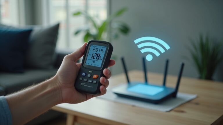
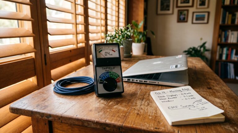
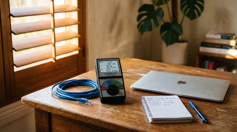
The TriField TF2 EMF meter measures all three field types relevant to solar inverter emissions: AC magnetic (50 Hz, the dominant inverter emission), AC electric fields (from wiring runs), and RF (from any Wi-Fi data logging module on the inverter). It reads in µT for magnetic fields, which aligns directly with both ARPANSA limits and Building Biology SBM-2015 thresholds. No conversion needed.
For dirty electricity specifically, the TriField TF2 does not measure high-frequency voltage transients on mains wiring. You need a dedicated meter — the Stetzerizer Microsurge Meter or an oscilloscope with a line-impedance stabilisation network (LISN). This is a more advanced measurement. Start with the TF2 for magnetic and electric fields. If those are within acceptable ranges and you still have concerns, dirty electricity measurement is the next step.
Measurement Protocol
Step 1: Timing. Measure during peak solar generation — midday, clear sky, when your system is producing maximum output. Your inverter’s magnetic field is proportional to its power throughput. A 5kW inverter producing 4.8kW at noon will emit far more than the same unit producing 500W on a cloudy morning. Check your inverter’s display or monitoring app to confirm it is near peak output before you start.
Step 2: Baseline. Turn your solar system off at the DC isolator (the red switch near the inverter). Take a background reading at the inverter location and at your bed position. This is your baseline — it tells you what the ambient magnetic field is from other sources (street transformer, underground power, appliances). Write these numbers down.
Step 3: Active measurement. Turn the system back on. Wait 2-3 minutes for full power ramp-up. Take readings at: (a) 30 cm from the inverter face, (b) 1 metre, (c) 2 metres, (d) at the nearest bedroom wall, and (e) at your pillow position. Record each reading. The difference between your baseline (system off) and active (system on) readings is your inverter’s actual contribution.
Step 4: Wiring run. Use the TF2 in AC magnetic mode and trace the cable from the inverter to your switchboard. Hold the meter 10-20 cm from the wall surface. You are looking for elevated readings along the cable path. If the AC output cable from your inverter runs through a bedroom ceiling cavity, you will see elevated magnetic field readings along that path. This is addressable by having an electrician re-route the cable.
Step 5: Interpret. Compare your bed-position reading to the Building Biology SBM-2015 thresholds: below 0.2 µT magnetic and below 5 V/m electric = “no anomaly” for a sleeping area. If your readings exceed these during peak generation but your baseline (system off) is below, your inverter is the confirmed source — and distance or relocation is the fix.
Dirty Electricity: The Solar EMF Issue Nobody Talks About
Here is the part that most solar EMF articles skip entirely. Your inverter’s AC magnetic field is a local problem. Dirty electricity is a house-wide problem. And it is the emission type where solar inverters have the most measurable impact on your home’s electromagnetic environment.
Every inverter uses pulse-width modulation (PWM) or similar high-frequency switching to convert DC to AC. This switching happens at 16-50 kHz depending on the inverter model. The output waveform is filtered to approximate a clean 50 Hz sine wave, but no filter is perfect. Residual harmonics at the switching frequency and its multiples (32 kHz, 48 kHz, 64 kHz, etc.) pass through the inverter’s output filter and onto your household mains wiring. These high-frequency voltage transients — measured in millivolts or Graham-Stetzer (GS) units — propagate throughout your entire electrical system.
Pre-solar vs post-solar measurements tell the story. Building Biology practitioners typically report pre-solar dirty electricity levels at bedroom power points of 30-80 GS units. After a 6.6kW solar system installation with a Fronius string inverter, daytime readings at the same power points commonly rise to 100-400 GS units during peak generation. The Building Biology SBM-2015 guideline considers below 50 GS units “no anomaly.” Above 100 GS units is “slight anomaly.” Above 500 is “severe anomaly.” A typical solar installation pushes most Australian homes from “no anomaly” to “slight” or “strong anomaly” territory during daylight hours.
At night, when the inverter is not generating, dirty electricity levels drop back to pre-solar baselines. This is actually useful information: it confirms the inverter is the source and it means your sleeping hours (if you sleep after sunset) may not be affected. But in summer, with sunset at 7:30 PM and sunrise at 5:00 AM in south-east Queensland, your inverter is generating — and injecting harmonics — for up to 14 hours of the day. If you work from home, you are exposed during your entire working day.
Mitigation Options for Dirty Electricity
Stetzerizer filters are plug-in capacitive filters designed to absorb high-frequency transients between 4 kHz and 100 kHz. They plug into standard power points and reduce GS meter readings. A typical home needs 15-20 filters to bring readings below 50 GS units across all circuits. At approximately $40-50 per filter, that is $600-1,000 for a whole-house treatment. They work — the manufacturer reports meaningful reductions in GS readings at treated power points. The limitation: they filter symptoms, not the source. They also draw a small amount of reactive power and can occasionally interact with sensitive electronics.
Line-conditioner at the inverter output is a more targeted approach. An EMI line filter installed between the inverter’s AC output and the switchboard can attenuate conducted emissions before they reach your household wiring. This requires a licensed electrician and costs $200-500 for parts and installation. It addresses the source rather than treating every circuit individually. Ask your solar installer about this option during installation — it is far cheaper to add during initial wiring than retrofit later.
Inverter selection matters. Not all inverters produce the same harmonic profile. Fronius inverters have generally tested well for low harmonic distortion in independent assessments. Some cheaper inverters — particularly those that barely meet AS/NZS CISPR 11 limits — inject significantly more high-frequency noise. If you have not yet purchased your system, choosing a quality inverter from Fronius, SolarEdge, or Enphase is a meaningful EMF decision.
Battery Storage Systems: Additional EMF Considerations
If you have or are considering a battery system — Tesla Powerwall, BYD, Sungrow, Enphase IQ — you are adding another power electronics device to your home. Battery inverters (or hybrid inverters that handle both solar and battery) produce their own AC magnetic fields and inject their own harmonics onto the mains, and they do it at night when your solar inverter is idle.
A Tesla Powerwall 2 mounted on a garage wall produces approximately 0.3-0.8 µT at 1 metre during charge and discharge cycles. The critical difference: it operates 24/7, including overnight when you are sleeping. If your Powerwall is mounted on the wall directly behind your bedroom, you have a continuous magnetic field source that does not switch off at sunset like the solar inverter does. The same placement rules apply: 2+ metres from any sleeping area, preferably in the garage.
Hybrid inverters (units that manage both solar input and battery charging/discharging, like the Fronius GEN24 or Sungrow SH series) concentrate both functions in one box. The magnetic field output is comparable to a standard string inverter during the day but continues at reduced levels overnight during battery discharge. If you are upgrading to a hybrid system, this is the time to address inverter placement — you only get one chance to install it in the right location without paying for a costly relocation.
The Smart Meter Interaction
Your solar system connects to the grid through your electricity meter, which in most Australian homes is now a smart meter. In Queensland, Energex smart meters operate at 900 MHz in a mesh network, transmitting data in short bursts. In NSW, Ausgrid meters use the same frequency band. These meters transmit regardless of whether you have solar — but a solar installation often triggers a smart meter upgrade if you still have an old analogue meter.
The EMF concern with smart meters is RF, not magnetic fields. Peak RF readings from an Energex smart meter at 30 cm can reach 5-50 µW/cm² during a transmission burst, dropping to near zero between bursts. At 1 metre, peak readings are typically 0.5-5 µW/cm². The ARPANSA limit at 900 MHz is approximately 450 µW/cm² — well above actual readings. The Building Biology SBM-2015 sleeping-area guideline for RF is below 0.1 mW/m² (0.01 µW/cm²), which can be exceeded at distances under 2-3 metres during peak bursts.
If your smart meter is on the exterior wall of your bedroom — common in Australian homes — this is a separate EMF source that compounds with your solar inverter’s emissions. The TriField TF2 can measure the RF bursts in its RF mode. Use peak hold to capture the transmission burst, not the time-averaged reading. Smart meters transmit in bursts — peak readings can be 100-1,000 times higher than the time-averaged value.
The fix is the same as for the inverter: distance. Move your bed to an interior wall away from the meter. If the meter is on the same wall as the inverter, you have two sources on one wall — and relocating the bed becomes the priority action.
Action Checklist: Reducing Solar Inverter EMF in Your Home
Here is the exact sequence, in order of impact and cost. You do not need to do all of these. Start at the top and work down until your measurements show acceptable levels.
- Measure first. Buy a TriField TF2. Take readings at your bed position during peak solar generation. Compare to Building Biology SBM-2015: below 0.2 µT magnetic, below 5 V/m electric. If you are already below these, stop here. Your placement is fine.
- Distance the inverter. If readings exceed thresholds, relocate the inverter to a garage wall with no bedroom adjacency (~$300-600 for electrician re-route), or move your bed to the wall furthest from the inverter (free).
- Check the AC cable run. Trace the cable from inverter to switchboard with the TF2. If it runs through a bedroom ceiling, have your electrician re-route it.
- Address dirty electricity. If you have a dedicated dirty electricity meter, measure at bedroom power points during peak generation. If above 50 GS units, consider an EMI line filter at the inverter output ($200-500 installed) or Stetzerizer filters at affected power points ($40-50 each).
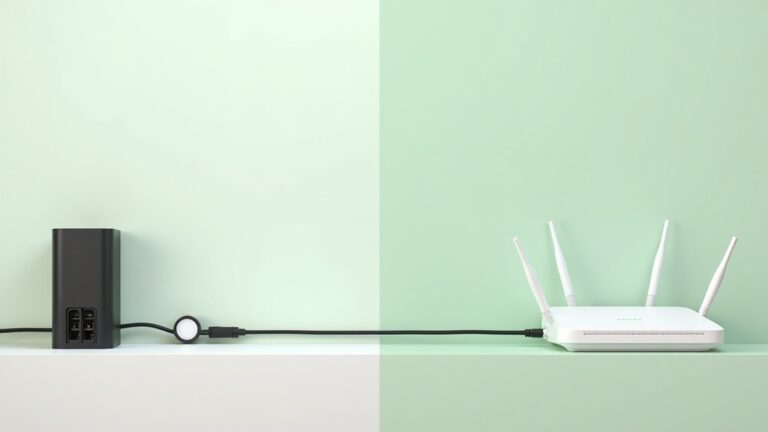
- Disable inverter Wi-Fi. Most Fronius and Sungrow inverters have Wi-Fi data logging enabled by default. If you do not use the monitoring app, disable Wi-Fi in the inverter settings. Use a wired ethernet connection for monitoring instead, if available. This eliminates the inverter’s RF emission entirely.
- Address the smart meter. If your meter is on a bedroom wall, move the bed to an interior wall. Use the TF2 in RF peak hold mode to measure smart meter burst emissions.
- Bedroom Wi-Fi timer. While you are optimising your sleeping environment, plug your Wi-Fi router into a mechanical timer ($20) to cut RF during sleep hours. Phone on airplane mode. These two actions, combined with inverter distance, address the three largest EMF sources in most Australian bedrooms.
Last reviewed: August 2026 — Clean and Native
Start with measurement. The TriField TF2 is the only meter you need.
Measures AC magnetic, AC electric, and RF in one device. Without real readings from your inverter during peak generation, every EMF decision is a guess.
Frequently Asked Questions
Do solar panels themselves emit EMF?
Solar panels produce DC electricity, which generates a static magnetic field — not the alternating (AC) magnetic field that is the primary concern. The DC magnetic field from rooftop panels is extremely weak (typically below 0.01 µT at the ceiling surface) and is not considered a health concern by ARPANSA or Building Biology practitioners. The inverter, which converts DC to AC, is the emission source that matters.
How far should a solar inverter be from a bedroom?
At least 2 metres from any sleeping position, measured through walls. At 2 metres, most residential string inverters (5-10kW) produce magnetic fields below the Building Biology SBM-2015 sleeping-area threshold of 0.2 µT. Three metres or more is ideal. Verify with a TriField TF2 during peak generation.
Does a Fronius inverter emit more EMF than a SolarEdge?
At the wall-mounted inverter unit, both produce comparable AC magnetic fields of 0.4-2.0 µT at 1 metre during peak generation. SolarEdge adds power optimisers on the roof that create additional small magnetic fields (0.1-0.3 µT at 30 cm per optimiser) and use power line communication on the DC wiring. In practical terms, the total EMF exposure difference between the two is small — placement matters far more than brand.
Can I shield my bedroom from solar inverter EMF?
Shielding 50 Hz magnetic fields is extremely difficult and expensive. Mu-metal shielding can attenuate magnetic fields but costs thousands of dollars and requires professional installation. Standard materials like aluminium foil, EMF paint, and copper mesh do not block 50 Hz magnetic fields — they only work for RF and electric fields. Distance from the inverter is far more effective and far cheaper than any shielding approach for magnetic fields.
Does my solar inverter emit EMF at night?
A solar-only inverter produces near-zero magnetic field at night because it is not converting power. Standby electronics draw minimal current. However, if you have a battery system (Tesla Powerwall, BYD, Sungrow) with a hybrid inverter, the inverter operates 24/7 during charge and discharge cycles — including overnight during sleep. Battery systems extend EMF exposure from daytime-only to continuous.
What is dirty electricity from solar inverters?
Dirty electricity refers to high-frequency voltage transients (typically 2-100 kHz) that solar inverters inject onto household mains wiring as a byproduct of the DC-to-AC conversion switching process. Unlike the localised magnetic field, dirty electricity travels on your wiring to every power point in the house. It is measured with a Stetzerizer Microsurge Meter in Graham-Stetzer (GS) units. Pre-solar homes typically read 30-80 GS units; post-solar homes often read 100-400 GS units during peak generation.
Does ARPANSA consider solar inverters safe?
Yes. According to ARPANSA measurement surveys, residential solar inverter magnetic fields at typical installation distances fall well below the general public exposure limit of 1,000 µT at 50 Hz. However, ARPANSA’s limit is a thermal safety standard — it protects against acute heating effects, not long-term low-level exposure. The Building Biology SBM-2015 precautionary guideline for sleeping areas is 5,000 times more conservative at 0.2 µT. Both standards are factually correct; they serve different purposes.
Are microinverters better or worse for EMF than string inverters?
Each Enphase microinverter produces a smaller magnetic field than a single string inverter, but the fields are distributed across your entire roof rather than concentrated in one manageable location. Microinverters also inject harmonics from multiple points simultaneously, creating a more complex dirty electricity profile. For single-storey homes with bedrooms directly below roof panels, string inverters offer more control because you can distance the single box from sleeping areas.
Can I turn off my inverter’s Wi-Fi to reduce EMF?
Yes. Most Fronius, Sungrow, and GoodWe inverters have Wi-Fi modules that can be disabled through the inverter’s settings menu or installer interface. Disabling Wi-Fi eliminates the 2.4 GHz RF emission from the inverter. You can still monitor your system via a wired ethernet connection if your inverter supports it. This does not affect the magnetic field or dirty electricity emissions — only the RF component.
How do I measure dirty electricity from my solar system?
Plug a Stetzerizer Microsurge Meter into power points throughout your home and take readings with the solar system on (midday) and off (DC isolator switched to off position). The difference between on and off readings isolates the inverter’s contribution. The Building Biology SBM-2015 guideline considers below 50 GS units “no anomaly.” The TriField TF2 does not measure dirty electricity — it requires a dedicated meter.
Get the Australian Home Environment Checklist
30 checks across water, air and EMF. Most of them free. Ranked by impact.
No spam. Unsubscribe any time.

Former Royal Australian Navy Clearance Diver and TAG-E counter-terrorism operator. Founded Clean and Native to apply the same rigorous thinking to the home environment.
Full biography →